Monday, October 13, 2025

2M low-pass filter

 I'm putting together a 2m Fox (for Fox Hunting), and I needed a 2m low-pass filter.  I copied what was done here.


Measuring 

-.69dB at 145MHz.

-3.7dB at 174.2MHz


Knocking down the spikes

Before:


25.2@145MHz

-13db@292MHz

12db@433

-9.8@586MHz

2.3db @733MHz

-7@879MHz

After:


25.2@145MHz

-20db@433MHz

-20db @733MHz


Sunday, May 18, 2025

SSB Single-conversion superhet transmitter


Juggled some wires from the receiver I made yesterday to get a transmitter.  The video shows me picking up the signal on my G90 (I'm transmitting into a dummy load).

My signal path is going microphone to the input of the first Si5351 (where the antenna was coming in on the receiver).  I switched the wires coming out of the Si5351 (so I didn't have to reprogram anything for now), so the ~9MHz is going into the first mixer and the ~5MHz is going into the second (opposite of the receiver).

I'm using this Adafruit board that has an electret microphone and amplifier together.  I made a little board that has a blocking cap (22uF - what I had handy) to block the DC bias the board has.  In the configuration, it is doing 60db gain and is enough to get 80mv P-P to the dummy load (~ -18dbm).  Will probably need to use another amplifier to drive the QRP Labs 10W linear amp.

Saturday, May 17, 2025

SSB Single-conversion superhet receiver


I strung together a bunch of parts to make an SSB receiver.

Details (mostly for my later reference)

  • Currently set up for 20m
  • Bandpass filter is the QRP Labs design, just with parts I had laying around.  Don't have as nice of capacitors as his kit (they are no-name trimmer caps) and the bandwidth is more like 2MHz vs his 1.4MHz, but the insertion loss was about the same (-1.75dB) and does the job.
  • I have one RF amplifier in - an AliExpress "low noise 30db" thing.  (I need to remeasure what gain I'm actually getting at 9V.)  Will probably replace for a MostlyDIYRF IF amp that has AGC.
  • Both mixers are AD831 boards off of Aliexpress.  Want to see about swapping them out for some of the DBMs I built when playing with the SolderSmoke DCR.
  • The audio amplifier is one from SparkFun, a class D amp based on the TPA2005D1 chip.
  • The speaker is a Jameco Valuepro "4" 8 Ohm 5W 800Hz-10kHz Paper 97 dB"
  • The IF bandpass filter is the Mostlydiyrf one that I posted about before.  I made little stand-alone matching transformers for it.  I'll probably swap it out for a similar crystal filter I made years ago.
  • The VFO/BFO is from a MostlyDIYRF "UDVBM-1 Universal Digital VFO/BFO".  Will replace with my own arduino/si5351/display setup if I actually box this up, as this board is really nice for mocking things up and would like to keep it out for that.  Also, the code he has for this has a few things I'd change (the VFO shows the actual frequency, not the frequency+BFO, and the "click to change what digit you are changing" doesn't go high enough).  There are a lot of libraries out there or might roll my own.
No matter how many times I think about it, figuring out what side of the IF filter to put the VFO/BFO always does my head in, and of course I had it on the wrong side to start.  I like using FT8 to test, as you always know there are going to be strong signals there, and if my iPhone decodes it, we're probably good to go.

I think next step is that I want to make it a transmitter.  Really just need to make an amplifier for the microphone, use the QRP Labs 10W amp (must remember to take out the 40M bpf it has in it).  Use one of my various RF amps to get the power up enough to drive that.  I have various LPFs I've made over time sitting around.

Then see about making it a transceiver.  I have some relay modules that are ready-to-use with microcontrollers (have the diodes in for the current spike, etc.)  I think will be mostly figuring out how I want to attach different parts, updating the code to handle switching, etc.  The whole "boxing and socketry" thing is the part I'm least good at, so might take quite a while to get to it.

Anyway was well pleased 

Saturday, May 3, 2025

Playing with a new crystal filter

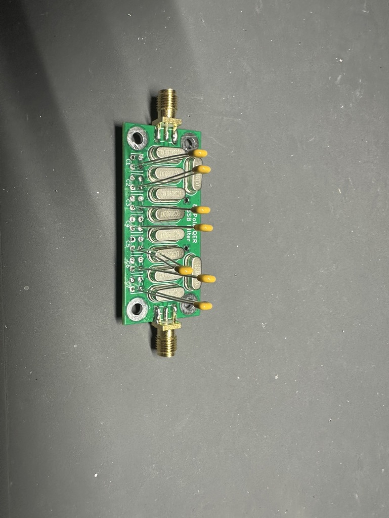
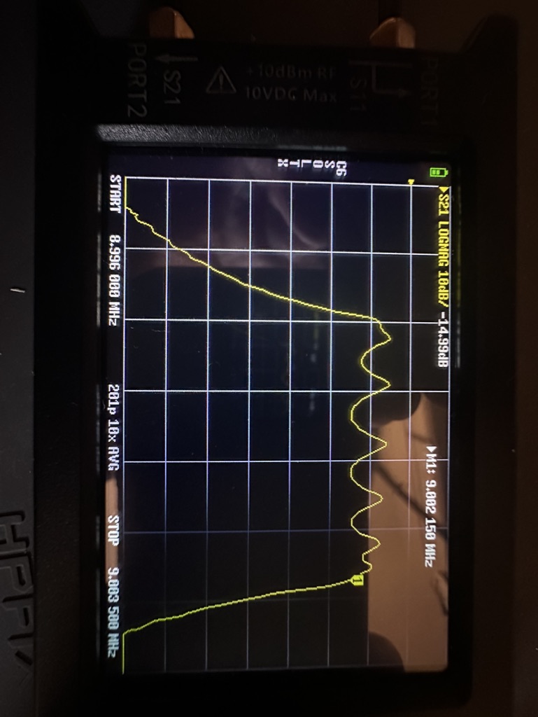
 I recently put together this board - I wanted a crystal filter that looked a bit neater than the one I built previously.  Here is the board and it's frequency response directly.


That is a lot of ripple, as the filter does not want to "see" 50 ohms.  The email from the vendor said that this has an approximately "native" impedance of 150 ohms.  So I made input/output transformers to get to approximately that.  Was better, but still a lot more ripple than I wanted.

I found this post talking about matching the impedance of the filter to fix the filter's response.  It didn't click at first exactly the procedure, but eventually got it.  Inserting a resistor in series with the filter increases the impedance it "sees", and the filter response adjusts accordingly.  So I made to little fixtures of sma connectors with an in-line potentiometer.  The only ones I had were 10k, so it was touchier than I'd have liked.  But found the impedance looked more like the 300-400 ohm range.  Note that the impedance the filter "sees" is the amount of inline resistance + 50 ohms (from the nanovna).


I made a new transformer that had a 7:20 turn ratio, and got a much better result.  (So far have only made one on the input, still using the lower-impedance 5:9 transformer on the output.)


The bandwidth is 3.8KHz at the moment.  I need to have a play with the other capacitors provided to get the value down to something better.  (This is why the caps are on there the way they are at the moment - to easily remove them to try others.)  


Sunday, March 30, 2025

Quick Pi Pico TX test

 Changed the hardcoded frequency to the WSPR frequency, threw on an AliExpress 2W amp and a QRP labs LPF, and used the transmit feature of the iOS "WSPR Watch" software (just holding my earbud up to microphone.  


Saturday, March 29, 2025

Pi Pico SSB transmitter


I threw together the Pi Pico-based SSB transmitter from here.

I haven't had a chance to do much with it yet, but got immediate results and was very pleased to hear myself over my G90 from it.

Sunday, January 19, 2025

Preliminary success with new devices

 A nice chap that goes by Stretchyman put me onto some devices I was not aware of.  Specifically, the UCC27614DR gate driver and the GAN111-650WSBQ GaN FET.  I had a go this afternoon with throwing them together in a similar layout as my last try with the IRF510.

So far I'm getting good results.  Out of the gate I was getting 10W out with decent efficiency.  I haven't let it run long yet.  

As an aside, I noticed that my probe was having an effect when I put it on the dummy load.  Switched it to 10x and that fixed that.


Sunday, January 12, 2025

A lot of progress over the weekend

 I haven't been writing this down, so it is hard to remember all I got done over this weekend.

I spent some time trying to build this HF PA.  


I was not getting at all the output that I was expecting.  And also found that the drive waveform looked weird.  The guy who designed it was super nice and responded to my emails really quickly, but I couldn't quite figure out what was up.  But I did observe a few things

  • The drive waveform was "weird" when using my signal generator.  But it looked way better when I used the SI5351.  I'd like to investigate this more later.
  • The drive still wasn't as square as I'd like.  My theory is it is due to my construction technique introducing stray capacitance/inductance.  Want to look into rebuilding (maybe a pcb)
  • Even when I increased the power to the drain, the output power didn't increase.  Don't know what was up there.  One theory is that this isn't a good IRF510 - it was one from Radio Shack years ago, and I couldn't find my new ones anywhere.  Want to order new ones and try it.
  • I built a little adapter board where I could use 3 BS170s in place of the IRF510.  It does look like increasing the the drain voltage increased the power out here, which points to the IRF510 being bad.  But also want to investigate to make sure I didn't do anything dumb with the output transformer.

I also wanted to try the NCP81074A again.  This time I decided I would try with an actual PCB.


First time I've etched a PCB this century.  I have tried a few different toner transfer techniques (acetone/alcohol no-heat, various papers for heat transfer).  I ended up trying this paper, and it worked pretty well.  I don't think Brother's are supposed to be best for this, and my toner is running low, but it turned out ok anyway.  I used an iron on high for two minutes.  The edges weren't great and there were a few lines broken, so I filled in with Sharpie.  I used ferric chloride with a sponge (so I barely used any, and it was done quickly).  I checked with meter, and there was only one broken trace (that I fixed with solder).


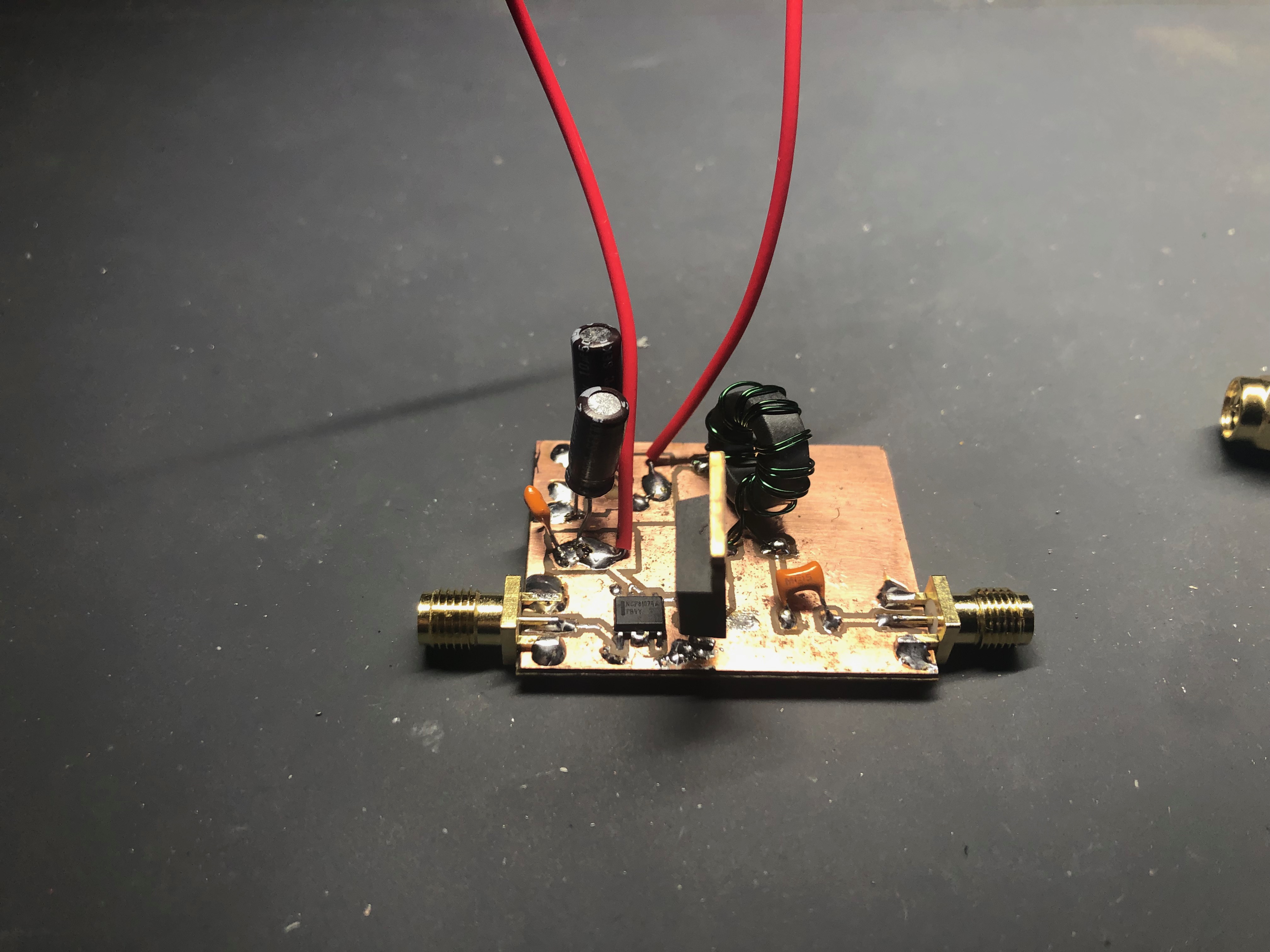
And here it is populated.


Got nice results - looks like 85% efficiency.  I tried some different voltages, could get 10+ watts out.  I ended up putting a heatsink on, but turned it back down to 5W.  I can't quite tell how how the driver gets, and at 14MHz it seemed pretty toasty.  Will play more with different drive voltages, etc.

Overall, a nice result for the weekend!


Tuesday, January 7, 2025

10W amplifier - success!

 Woke up early this morning so was able to swap out the BS170s before work.  The hardest part was figuring out where they were :)

Well, also desoldering.  The wick works good in general, but isn't good at clearing holes.  But I managed to use the soldapullt on the other side of the board from the iron and it worked a treat.  Would have been good to have a third hand or a helper, but made it work.


On the plus side, I have output!  And gain!  But not as much gain as I should have.  

With a 13.8V power supply and 9v p-p from the signal generator, I was getting about 4.6W out (15.2 vrms).  I am unclear on if that is too much power input.  There are discussions on the forums about input impedance not being 50 ohms, so I'm not sure if that is 200 mW (at 50 ohms) or 25mV (400 ohms).  Should try to get a proper power input measurement...

But based on things in the forums, I increased the power, and was able to get 10W at 17v.  Can experiment more with the input power.  But, regardless, I fixed it!  :)


Monday, January 6, 2025

Another go at a QRP Labs 10w Linear amp

 I had a great time at the Minnesota Amateur Radio Technical Society meeting this past Saturday.  Great conversation, and free stuff to boot!  A beloved member had recently become a silent key (at almost 100), and his family had sent a bunch of his workbench stuff in to go to a good home.

Most interestingly, there was a 10W amp!

This is a QRP Labs 10W linear amplifier.  Which I know about because I've built one, but never got it quite working.  (I can't find my notes about the issues I was having).  So this is exciting.


First of all, Mert did a way better job of boxing things up than I ever have.  


On the inside, I found that there was a low pass filter on the output.  Measuring with the vna, it looks like it is for 7MHz.  Also, the transmitter powers the bias when the /tx pin is low.  He has a phono jack for this, and made a little shorted plug to keep it on.  Nice!

I hooked it up to a dummy load and powered it on with no input, and it looks like the bias is already set correctly.

Unfortunately, when I applied signal, nothing came out the other side.

Poking around, the bias at the irf510s looks right, but there was no signal.

The input BS170s have power and signal, but no output.  So, those look blown.  It got late tonight, so I'll have to wait to swap them out for another day.


Friday, January 3, 2025

Towards a working class E amplifier

 I've had a few attempts in the past of building a class E amp, but never quite got the right results.

I dug out an old board where I tried to replicate the NS-40 and decided to try a different drive circuit.  I took out the oscillator and drive circuitry and replaced it with a NCP81074A gate driver.

It somewhat worked - I was able to get some power out.  But it isn't as efficient as it should be because the gate drive is ugly.  Need to look into it more.


The circuit


The ugly gate drive


Monday, December 23, 2024

Double-tuned bandpass filter

I made a bandpass filter the other day, but was having difficulty getting it exactly like I wanted messing with the turns on the coil.  Thought it would be nice to have one that I could tune.  Of course, N6QW had something for this.  But the transformer he suggested wasn't available through Mouser any more.  He had a vendor out of the UK, but the shipping was pretty high for just the parts I wanted.

Then later I was looking on Aliexpress, and came across the very thing.  A seller by the name of
"Bohinda inductance coil Store" manufactures the exact thing (their part name is "(7E )42IF123A").  They will also manufacture to your spec and also have "blank" ones for you to wind your own.

I quickly threw together one for 30M (since I didn't want to bother taking the capacitor out for 20M).  Also tried my hand at winding one.  (I got a different design for the build-your-own on accident, but turned out well.)


Sunday, December 1, 2024

SSB Success!

Woke up way too early this morning, and ended up watching a bunch of YouTube videos.  One of them I came across was this, which made me realize I had been using the wrong BFO frequency for my radio!  Adjusted things, and I can hear people!  I was doing the BFO on the wrong side of the filter, getting frequency inversion.  For the amount of times I heard n2cqr talk about it, you think I would have gotten it right!

The voices were super quiet - don't have the right gain in the right places - but I could hear it!  I've also got a bit of a ground loop I think, so I had to make sure I was touching the audio amp potentiometer or my amplifiers became oscillators.  But at least now I know I'm not crazy - I really couldn't figure out why I wasn't hearing what I expected.

For my reference, here are the frequencies.  I am doing the 20M band, and the BFO (ch2 here) is at the top end of my crystal filter.  (I measured it the other day as going from ~8.9967 to ~8.9986.)


Saturday, November 30, 2024

Testing a filter with noise

 I built a noise generation circuit out of EMRFD ages ago, but I don't think I ever did much with it.  I was looking at my crystal filter today, and thinking how the TinySA is limited in its minimal bandwidth.  Then I remembered I had an SDR and could look at it with that.

I was using CubicSDR, and the display isn't as clear as I'd like.  Would like if I had some averaging to give me a nice picture, may look into that.


Monday, November 25, 2024

Beautiful sounds from my ssb receiver

 
I started building an SSB rig ages ago.  Or at least the parts of it.

I build the crystal filter and the various amplifiers over three years ago.  And I had the mixers (ADE-1), audio amp (one of these left over from a defunct synth project), and the VFO/BFO (an SI5351 board/Arduino) ready to go.  I got it partially wired up and then... stopped.  My interests are a fickle thing.

Anyway, I wired it up, tweaked a lot, and can sort of, kind of hear stuff!  


the most beautiful radio in the world

I haven't been able to make out any people yet, but have heard some code, and I managed to decode FT8 using the iFTx app on my iPhone!


You'll notice in the top picture, I am using my signal generator.  I had mis-remembered some things about the SI5351, so I had a pad in front of it, which was not getting the mixer to the +7dbm it needed for LO.  So in debugging I used my signal generator and just stuck with it.

I may want to try some other configurations (like actually make a BPF for the front, and maybe a LNA in front of that) and might try some more gain in the middle (between the filter and the product detector).  But pretty pleased it is working at all.  Also need to have a bit more of a think around where exactly I want the VFO/BFO.  Lots more to do, but pleased where it is.


Sunday, November 10, 2024

Quick and dirty L match tuner

After having good success with the little wspr thing I put together, I decided to put up my old end-fed half-wavelength qrp antenna outside.  I still have a under-window coax connector, so strung it up between my workshop window and the garage across the driveway.  Got much nicer results.


I did notice though that it was resonating low - it was more like 13.5 rather than 14MHz.  I need to adjust it, but it was already dark.  So I decided to have a play with throwing together an antenna tuner real quick.

I took the 3D printed variable capacitor I made a while back, wrapped some wire around an inductor (making taps every once in a while, and threw it together on a little board I made the other day to hold my low-pass-filter.  I'm using an alligator clip to adjust the inductance (choosing different taps on the inductor).


I managed to tune it for 7MHz ok. 


Was having trouble dialing in 14MHz - I think I needed more inductor value choices, and maybe the ability to go lower on the capacitance.  I could have a play with some switches to switch caps in, but this was more just an excuse to put one together, as I've not built one before.  Probably won't use it, but was fun.


Saturday, November 9, 2024

Long time, no ham


 I haven't done anything radio related in quite a while.  The past few weeks though I have started poking at stuff again.


I started off building a QRP Labs QDX.  Build went ok, but I keep having an issue where it restarts when I transmit.  I need to debug it more.  But I didn't feel like debugging it, so instead I thought it would be fun to just build the transmit chain.  


Not working great, either.  Probably the stray wires are a bad idea.  Should have built it ugly/Manhattan.

But I got enamored with the drive chip.  I had some 74AC240's sitting around, so built one like was done here.  


I figured while I was at it I should try it out by itself, so put together a 20M lpf, and built up a little board with an SI5351, and made a little wspr transmitter using the gist here.  Pretty sure I used the same one years ago.  


Didn't expect much since I just threw an old efhw antenna around my office.  Checked with my vna and saw it was resonating low (more like 13.5MHz), and was like 2.5:1 at the wspr frequency, but tried anyway.

When I going into a dummy load, it was doing around 1.4V rms, so I think it was only doing 40mw, and with the mismatch less than that.  Still, got picked up.  WSPR is pretty much magic.


I might try to put a transformer after the `240 to lower the impedance it is seeing to get more power out, but ran out of time.  

Also somewhere in the past few weeks, I got a neat BM83 dev board.  I wanted to see if I could use iFTx working via a bluetooth connection.  Unfortunately, I didn't really fully understand the various BT profiles.  The only bidirectional one (before the latest BLE "gamer" profile) is the headset profile (HSP), which is pretty low quality.  I think it would have been enough, but the iPhone won't use that except when answering a call.  (You could access it via your own program, but that isn't what I wanted.)  I found a program that lets you route audio to it, but it doesn't use the microphone.  The only other option would be to use two bluetooth devices in A2DP mode (one source and one sink), but the iPhone apparently won't act as a A2DP sink for some reason.  ::sigh::  Wish I would have understood all of this before buying the dev board, but going through the exercises of trying to get this to work made me understand all of this a lot more than reading would have I think.


Sunday, December 11, 2022

JS8Call and 15m Activity

 Used JS8Call I think for the first time today (though I already had it installed, so maybe I had tried it before).  Had to do some adjustments - it thought I had rig control on, and had to increase vox gain on the g90.  But responded to someone in California calling CQ and had a quick QSO.

Was trying 15m today on the small EFHW out the second floor window.  Did ok on WSPR.


Thursday, December 8, 2022

New Paddle

 Can't find my paddle.  But then kb9rlw posted a new design that was quick to make.