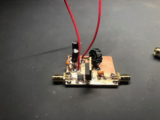
I haven't been writing this down, so it is hard to remember all I got done over this weekend.
I spent some time trying to build this HF PA.
I was not getting at all the output that I was expecting. And also found that the drive waveform looked weird. The guy who designed it was super nice and responded to my emails really quickly, but I couldn't quite figure out what was up. But I did observe a few things
- The drive waveform was "weird" when using my signal generator. But it looked way better when I used the SI5351. I'd like to investigate this more later.
- The drive still wasn't as square as I'd like. My theory is it is due to my construction technique introducing stray capacitance/inductance. Want to look into rebuilding (maybe a pcb)
- Even when I increased the power to the drain, the output power didn't increase. Don't know what was up there. One theory is that this isn't a good IRF510 - it was one from Radio Shack years ago, and I couldn't find my new ones anywhere. Want to order new ones and try it.
- I built a little adapter board where I could use 3 BS170s in place of the IRF510. It does look like increasing the the drain voltage increased the power out here, which points to the IRF510 being bad. But also want to investigate to make sure I didn't do anything dumb with the output transformer.
First time I've etched a PCB this century. I have tried a few different toner transfer techniques (acetone/alcohol no-heat, various papers for heat transfer). I ended up trying this paper, and it worked pretty well. I don't think Brother's are supposed to be best for this, and my toner is running low, but it turned out ok anyway. I used an iron on high for two minutes. The edges weren't great and there were a few lines broken, so I filled in with Sharpie. I used ferric chloride with a sponge (so I barely used any, and it was done quickly). I checked with meter, and there was only one broken trace (that I fixed with solder).


No comments:
Post a Comment