I recently put together this board - I wanted a crystal filter that looked a bit neater than the one I built previously. Here is the board and it's frequency response directly.
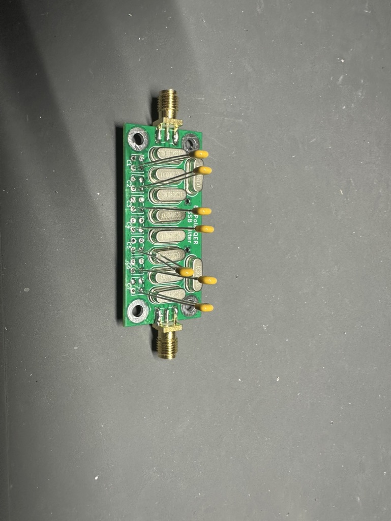

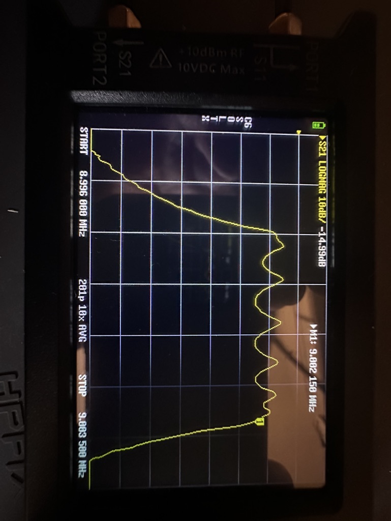
That is a lot of ripple, as the filter does not want to "see" 50 ohms. The email from the vendor said that this has an approximately "native" impedance of 150 ohms. So I made input/output transformers to get to approximately that. Was better, but still a lot more ripple than I wanted.
I found this post talking about matching the impedance of the filter to fix the filter's response. It didn't click at first exactly the procedure, but eventually got it. Inserting a resistor in series with the filter increases the impedance it "sees", and the filter response adjusts accordingly. So I made to little fixtures of sma connectors with an in-line potentiometer. The only ones I had were 10k, so it was touchier than I'd have liked. But found the impedance looked more like the 300-400 ohm range. Note that the impedance the filter "sees" is the amount of inline resistance + 50 ohms (from the nanovna).


I made a new transformer that had a 7:20 turn ratio, and got a much better result. (So far have only made one on the input, still using the lower-impedance 5:9 transformer on the output.)

The bandwidth is 3.8KHz at the moment. I need to have a play with the other capacitors provided to get the value down to something better. (This is why the caps are on there the way they are at the moment - to easily remove them to try others.)
No comments:
Post a Comment