Sunday, July 31, 2016

Power supply woes?

I built another little preamp today (this time just a CE followed by a CC rather than the shunt thing I used before), just to see if additional drive was the issue.  Did not seem to help.

However, it occurred to me that it might be the power source I'm using.  I've been using alkaline AA batteries.  But calculating things out, for 12v to produce 5 watts, the batteries would need to be delivering around half an amp (not counting what is dissipated in the transistors).  I always assumed that the batteries could deliver more amperage for a shorter time (the amp-hour rating).  However, I forgot that that batteries have voltage curves.  I measured the voltage output when the amp was running, and it was closer to 9V.  So, I think I need to go find a better battery to use :)

(I actually tried a wall wart, but I think I was either getting feedback into it or it was just noisy, was getting a weird output when I tried to bring the power above what I had with the batteries.)

Tuesday, July 26, 2016

Transmitter progress

I moved the circuit to copper, but no love.  Still when I turn the bias up, it all goes haywire.  Actually worse than before.  Thinking it might have to do with the drive level, I tried adding an amplifier stage ahead of the 2n3053, but again no love.

Then I thought "hey, I sure have a lot of wires running around here..."  I had been using hook-up wire to join my modules, as I didn't have any extra coax.  But I did get some recently, so I added some BNC connectors to the output of the PA and the input/output of the LPF.  Bam!  Pretty output!

I'm getting 20v P-P on about 11.3V power, which is about 1 watt.  I can get it up to about 1.5 watts by increasing the voltage to around 13V.  But I'm hoping for 5W.  Here at least some of the issue I think is the drive level.  I tried the little amp I had, but I think that was overdriving it.  Was getting about 3W out, but it was well ugly.  Will need to have a think about what the drive level ought to be.

I might at some point see about using a different IRF510.  I've read that "lower quality" parts may not work as well, and I'm not entirely sure about this one.

Edit: actually, after playing around in LTSpice, I think I may need to change out some of the coupling caps.  The ones he uses in the Mighty Mike look to be attenuating things too much.  In the simulation, if I change those to larger caps (closer to .1uf) and run it at the same power he does, I get >5W out, even with my current drive level.  With his values and my current voltage, I get closer to what I'm getting on the bench.

Edit 2 (next day): I tried swapping out the .001uf for .1uf coupling caps as I mentioned in the last post.  Raised the power some, but not nearly as much as in the simulation.  I also tried swapping out the IRF510 for a new one from Mouser, didn't see much change.

Friday, July 22, 2016

Another try at a transmitter

Trying a different approach, from the circuit here (pdf file).  This uses a 2n3053 to amplify an oscillator and drive an IRF510.

I built it out on a breadboard and after a lot of tinkering am getting about 0.7W out.  Which is nice and all, but for the voltage I'm using I should be getting twice that at the voltage I'm using.  Also, if I change out some of the coupling capacitors the plans use for some larger ones, it works even better in the simulator.  However, when I try to do it on the breadboard, it causes the DDS to stop working.  Not sure if there is some weird oscillations occurring there.

I think the big issues is that when I turn it on, the waveform going into the 2n3053 goes from a nice sine wave to something that has a lot of higher-frequency content.  Not sure what the cause of that is.  It could be just that the parasitics of the breadboard are causing it and that I should just go ahead and move it to copper, but I kind of wanted to get it working better before I did that.  Ho hum.

Tuesday, July 12, 2016

First steps towards a transmitter

I would like to add a CW transmitter to my little DC receiver.  I'm thinking of using an IRF510 running as a class C amplifier.

I got a 74AC240 to use as a driver for an IRF510.  However, the output of the DDS is fairly low.  I was going to use a comparator to convert to a 5v square wave, but was having trouble getting it to work.  I think the issue is that the LM399 I pulled out of the junk box isn't fast enough :/

I then tried making a Schmitt trigger out of an op amp I had laying around, but it wasn't fast enough either. One I tried was a bit faster, and if I got the source down to 1 Mhz it sort of worked.

Then I tried the DDS buffer to directly drive the '240 - success!  The buffer distorts a bit, so the signal out of the '240 isn't that great, either.  But I can clean that up with my low pass filter.  I'm measuring about 400 mW into a 50 ohm load when I use 5 volts on the '240.  I'm using a 12V source for the buffer and the Arduino's 5V output for the '240.


I seem to be running out of breadboard space.  Hopefully the IRF510 stage won't take up too much room.  Once I have something together that works, will see about moving the PA stage out to something more permanent.

Tuesday, July 5, 2016

antenna here is dipole

I finally got a chance to build and put up an antenna.  I followed on from the the ideas that WP4AOH had for building the center insulator, but added a 1:1 current balun as laid out in the W1FB QRP Notebook.  That calls for 12 bifilar turns of #26 wire on a FT50-43 for up to 25 watts.  I used #22 wire, as that is all I could find in my junk box.

Here is a closeup of the center insulator

And here it is living in a tree

It isn't very high - probably only 15 or so feet - but that is all I could manage right now with the arrangement of trees in my tiny back yard.  It is cut for 40M, and is sort of a bent inverted V.  It is about 100 degrees in the horizontal and slopes down to about 6 feet at the ends.  It is fed with 100 feet of RG-58.  No idea how well this arrangement will work, but will hopefully be better than the unmatched random wire I was testing the receiver with before.  I cut the legs too long and will shorten them once I have a method to measure it.

Also, many thanks to my wife and 5 year old for helping me measure, build, and raise the antenna.  I really lucked out in the family department :)

Thursday, June 2, 2016

CWAZ filter

Playing with the little buffer amp, I noticed the output was pretty messy - the 2nd harmonic was really high.  (Oddly, when I first built this without the output cap, it didn't look that bad.  But it was also putting out 6v p-p and probably would have burned out in a minute...)

I figured at some point I'd need to build a low pass filter, so this seemed like a good time.  Looking around, the CWAZ lpf design seemed popular, and I found this pdf from GQRP on how to build one.

I realized I was running low on called-for T37-6 toroids, as I used some in the DC receiver.  But then I remembered I cut one out to replace the VFO with the AD9850.  And it was already wound just like I needed!  How often does that happen?  The other two were fast to wind, and I picked out the capacitors from my junk box.


I hooked it up to the amplifier and looked at the output

Without filter

With filter
So, it looks a lot better.  Need to do some more experiments, but maybe ok?

P.S. I finally found out that "CWAZ" here stands for "chebyshev with added zero"

Tuesday, May 31, 2016

DDS Buffer

In order to see if I could get better readings on the antenna analyzer, I built this DDS buffer circuit from here.


First go of this I forgot the output cap, and when I hooked it up to my 50 ohm dummy load, I was getting 6 volts peak-to-peak.  I blinked a few times, confused, then checked the transistors.  HOT!

After the cap was added, it gave a more reasonable 3 volts p-p.  Not the prettiest output in the world - the first harmonic was pretty strong - but amplified.

I tried hooking this up to my antenna analyzer circuit and measured the result on the dummy load.


Hard to really see what is going on here, but it is DDS->Amp->Analyzer->Dummy load.  I'm still not seeing what I expect, though - the readings actually look worse.  I guess it could be that strong harmonic, not sure.

Antenna Analyzer

Doing my version of k6bez's antenna analyzer here (warning, pdf).

First, please notice that there are far more resistors on this board than there should be.  I could not find 50 ohm resistors anywhere on my workbench.  I ended up putting four 200 ohm in parallel.  (Also used two 10k in parallel for the 5k resistors, and used a 680 ohm instead of the 648(?!?) ohm he calls for.)

As a test, I just put the output of my VFO into this, measured the voltages out of the opamp with my DVM and calculated the VSWR in a spreadsheet against a couple of different resistor values.  Immediately noticed that where I should be getting 1:1 on a 50 ohm load, I was getting like 3.4:1.  Started poking around and found some cold joints in my bridge circuit.

Testing again, I get happier results.  However, they still aren't what I'm expecting.  I would expect a 50 ohm load to have a 1:1 reading, but is either 1.3 or 1.1 depending on what method I use to calculate (it should be (fwd + rev)/(fwd - rev), but I've seen people use the square of the individual values as well).

I saw some discussion on the Yahoo Group where someone was asking about the accuracy of the numbers.  They talk about the nonlinearity of the diode in there, and I also noticed in his slides that he talks about needing more power for accurate swr readings.  Maybe I'll make an amplifier next.


As a side note, something in my setup seems to be sucking down power.  Nothing is getting hot, but my setup browned out while I was testing.  Found the 9v battery I was powering this all off of was down to 7-ish volts.  I put in a new one, and in a few minutes it was down a volt, too.

Tuesday, May 17, 2016

AD9850 DDS VFO

You know when you have a project where you thought "I'll just throw some things together and see how it goes" and it works amazingly well on the first try?

I guess there is a first time for everything...

In any case, I got an AD9850 in the mail the other day, and I wanted to have a go at playing with it.  I found a bunch of write-ups of people doing this, but this one looked really well thought out.

I started out trying parts of his program, just to make sure I (a) understood it and (b) wired things right.  I started with the lcd and got hello world working.  Then I took his code and commented out most things to get the rotary encoder part working.  Then I wired up the whole thing and loaded up his code.  The only issue I had was that the for me, the include for the rotary code needed it spelled "Rotary.h" instead of lower case r.


After playing around with the step settings, etc, as he suggests in his writeup - I immediately got treated with a beautiful sine wave!

Encouraged, I started pulling the VFO components from my DC receiver I put together the other day.  I put the output of the DDS into pin 6 of the NE602 via a 10pF cap.  You can see the messy result here:


I excitedly turned on everything and attached a long wire to the antenna...  and I immediately heard code!!  The receiver is definitely crunchy (not enclosed, no filters, questionable antenna, etc), but it is super easy to tune with the digital VFO.  So excited!!

I'll probably play with this it in this form for a few days, but already trying to decide what to do next.  Thoughts include a bpf for the front end, some sort of narrow cw filter, and a simple agc circuit.  Oh, and maybe getting it off of a breadboard and into some sort of actual enclosure.

I want to thank Jan Ciger for sharing his awesome project!

Monday, May 16, 2016

Direct Conversion Reciever

I've been in a holding pattern on some other radio projects, so I decided to start another one - the "IC BASED DIRECT CONVERSION RECEIVER" from section 1.5 of EMRFD.  (Chapter 1 that has this project is online here.)  This is your basic ne602/lm386 combination you find lots of places.  I built mine for 40m.


The variable capacitors are little polyvaricons.  I got these cute little dials for them, but still need to find some screws to hold them in.

I threw some wire out the door and was able to hear some stations!  The thrill of hearing anything on a radio you built yourself is *awesome*.

Unfortunately, it is quickly replaced by the annoyance that it isn't doing *quite* what you want.  For one, it isn't quite on the frequency I want.  I made a rookie mistake and mounted the variable capacitors on veroboard (it was late and I was excited to be close to done...), which seems to have added a bit of capacitance.  I also found I had a wrong cap in somewhere.  So, I haven't quite got it to the 7-7.125 MHz range I was going for.


Also, it is *really* hard to tune.  I think a third padded down cap would help a lot, but getting it right on a station took a lot of practice.  Even as I got the hang of it, it was kind of harsh to listen to, and the whining as you got close to a station got old quick.

All in all, I'm counting this as a huge success.  But I don't think I'm going to keep it as is for long.  I got an AD9850 off of Ebay the other day that I think I'm going to try in place of the tuned circuit here.  Partially because I want to play around with the DDS, partially because the little variable caps here are fiddly.

This is my first Manhattan-style build, and I looked at a *lot* of examples before starting.  I need to give huge props to KK6GXG - his build was a huge inspiration.

Friday, April 22, 2016

Square wave test signal generator

I recently ordered parts from various sources, but haven't received them yet.  I was itching to build something, and I came across this little square wave test signal generator.


Just a little multivibrator to make a signal.  Since it is a square wave, you are going to get lots of harmonics.  The idea is that if you just need to put in *a* signal to see what comes out the other side (be it AF, IF, etc), this would be a quick little tool.

I didn't have a lot of free time today, so I decided just to get it working.  I needed to use a lower resistor value for RL1/RL2 as he mentioned - I guess the transistors I used didn't have as high of gain as his.  I used part of a paper clip for the probe, which worked pretty well.


I'm not sure when or if I'll actually use use this, but it got me my making fix for the day.  :)

Sunday, April 17, 2016

Measuring output impedance of the crystal checker

Just for fun, I wanted to see about cleaning up the output of the crystal checker.  I had fun putting different side capacitors on the output just to see what would happen on the output.  But I finally decided that I needed to measure the output impedance.  I had seen this video, but I was hung up on sizing the AC coupling capacitor first.  I asked on reddit, and an nice user pointed out that you want the cap to be low impedance at the frequency you care about.  (At which point I felt very silly for asking something so obvious.)

My fundamental frequency is at 3.57 MHz, so I calculated I need at least a 45nF capacitor.  I tried using a 470nF (what I had handy), and got an open voltage of 10.16v. Adding a 4.7k resistor off the other side of the cap as load, I got a voltage of 9.76v. So that would seem to say that my output impedance is 192.6 Ohms.

Thursday, April 14, 2016

Crystal tester - Fixed

I found this video on youTube, and he mentioned that the "4k7" on the schematic was suppose to be "47k".  I had a 4.7k there.  When I replaced it, I am seeing what I expect.  Yay!

Crystal tester

I built the crystal tester from here.


I am using a colorburst crystal, so the frequency should be 3.57954 MHz.  However, I seem to mainly see around 10Mhz.


Need to research a bit here - not sure why I'm not seeing the fundamental frequency I expect here.  Still, something nice to see on the scope :)

Wednesday, April 13, 2016

Noise Generator

After making the MMM, I was thinking about making a low pass filter to clean it up.  But having no toroids kicking around the garage at the moment, I was thinking about building all air core wound on forms.

But then I started thinking how to measure the LPF.  I started thinking about noise generators - feed broadband noise into the LPF, and look at the output on the FFT of the oscilloscope.  In theory, anyway.

I came across this circuit and decided to build it.  


Had several missteps (wrong resistor value, forgot to cut a trace, etc).  But after all that it still wasn't working.  I noticed in their writeup they mention that they got it from a different site, and when I looked at that one, I noticed they were using slightly different values (including a 12v source).  On a whim, I tried the higher voltage, and got noise!


I'm not sure if I'm getting as much noise as I want, though.  The output of this seems to be maybe 2v P-P.  If I'm reading the FFT right, it looks like the noise is up 30dBVrms.  But the FFT doesn't look to be going out as far as I would think.  If I'm reading it right, it is only showing me the fft out to around 600 KHz.  Strange.

After asking around and playing with the scope, I found that you need to adjust the horizontal time scale *before* you go into the Math function.  I also adjusted to use the maximum memory (under the horizontal menu) - not sure if that helped.

I think the next step here is to look at the output signal level and see if I can figure out how to go about increasing that - feels like that will be needed to really see signals when I try to measure filters.

Saturday, April 9, 2016

Quick and dirty dummy load

For a few projects, I was in need of a dummy load capable of handling a few watts.  I grabbed a few 2 watt resistors at Al Lasher's the other day, threw them on a protoboard with a BNC connector, and bob's your uncle.


Arduino inductance meter

I recently bought a little LC meter on EBay.  It was like $10.


When I got it, I immediately made a variable capacitor out of some aluminum foil, cardboard, and a piece of plastic so I could measure it.  Great fun.

Not long after, I was building the Mighty Mite, and thought "hey, here is a coil!  I should measure it!"

Nothing.

I thought maybe it was out of range, or there was some other reason it wouldn't measure.  But, it could also be that it just wasn't working for inductance.

So I decided to build a meter to compare with.

I didn't want to spend a lot of time reinventing any wheels, so I cast around for a design someone had already made.  There are quite a few out there, but I wanted to focus on quick and simple, and found this.


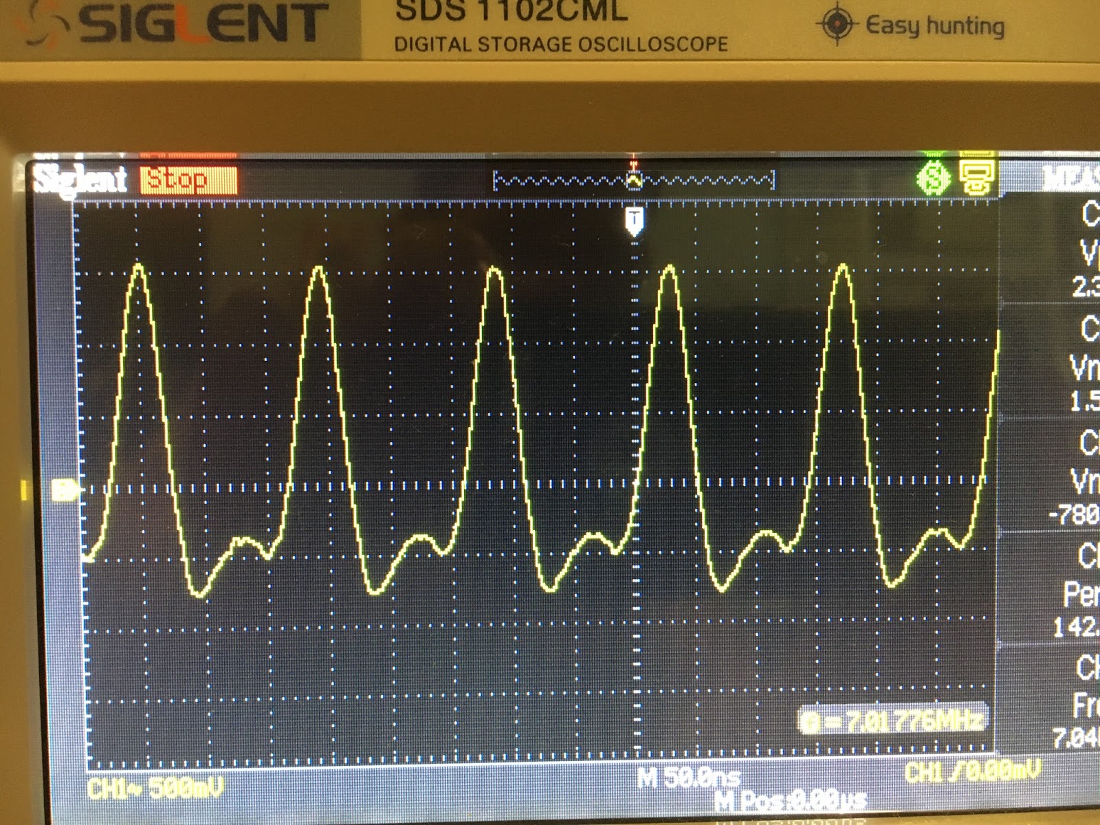
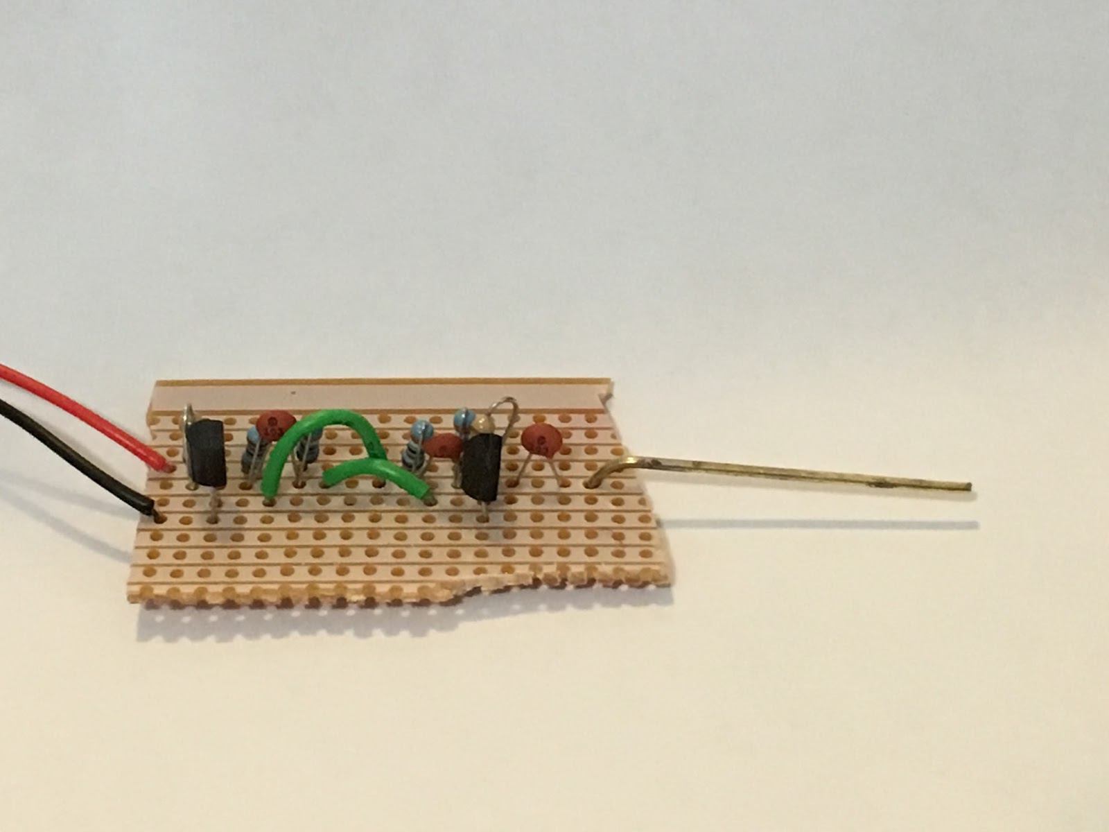
His page explains how it works really well.  Basically it is an LC tank formed between a known capacitance and your unknown coil.  It uses a comparator that I luckily happened to have in my junkbox.  I didn't have the 1uF caps, but I had some 0.47uF that I put in parallel.  My LC meter says that all together they equal 2uF, which is exactly what I needed.


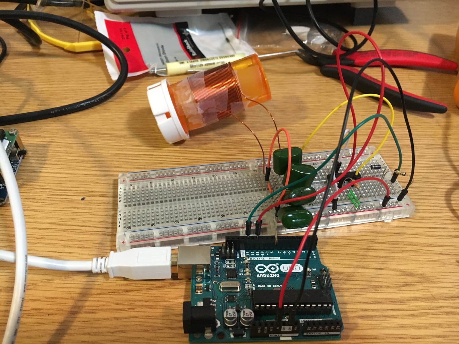
I wound some wire on a pill bottle to have something to measure.  I calculated that it should have an inductance of 31.1uH.  The Arduino measured it as 45.59uH.  The EBay device measured it as 0.

AND THEN...

Someone on the QRP-Tech Yahoo Group was asking about who had what LC Meters.  I mentioned I had this one that only measured capacitance.

A nice man by the name of Steve wrote me to ask if I shorted the leads when I first go to measure the inductance, as it requires that.  Um... no.  No I did not.  Now, to my credit, it didn't come with instructions and that isn't intuitive.  In any case, now that I know how to actually use it, it seems to work.

All in all, though, I'm glad I had the issue, because it gave me an excuse to wire up this project!

General class, with a side of Extra

I went up to Benicia today to take my General test.  I have been studying for it using the ARRL book and iOS app by N1ZTL.  I actually went through all the questions in the app and only missed a few, so was in good shape.  After I passed it, the VE encouraged me to take the Extra.  I didn't think that was going to work out, given there is a lot of information there and I had only read a bit in that book.  But it gave it a shot - why not, doesn't take long and didn't cost anymore.

AND I PASSED!

w00t!

Michigan Mighty Mite

Listening to the SolderSmoke podcast has convinced me that I need to experience the Joy of Oscillation.  To that end, I decided to build a Michigan Mighty Mite.


This is a simple CW transmitter circuit - basically a crystal oscillator circuit that can put a bit of power out on an antenna.  You can see how to build it here.  It only has a couple of parts.  I am using a pill bottle to build the transformer.  The transistor got a bit hot, so I'm using a soldering tool heat sink.  You can build it for many different frequencies.  I am using a 3.579545 MHz crystal, so perhaps I've joined the Color-Burst Liberation Army?


As you can see, the output is really ugly.  If I weren't doing this into a dummy load, I would definitely want to have a low pass filter on it.  Also, not sure how much the capacitance in the breadboard is contributing to matters.

I'm not 100% sure how much power it was putting out.  It looked like a paltry amount on the oscilloscope, but then I realized later that the probe was set on 10x and the machine was at 1x.  (I just got this, and I'm still learning the ins and outs.)  The coil got messed up in the interim, and think I'd rather move on to the next thing for now rather than play with it more.

Still, I got to experience the Joy of Oscillation, and I got to test out my new scope.  Good times!