I strung together a bunch of parts to make an SSB receiver.
Details (mostly for my later reference)
- Currently set up for 20m
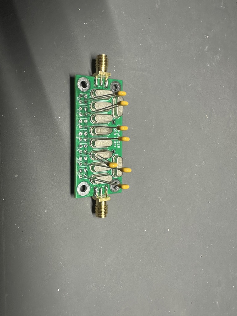
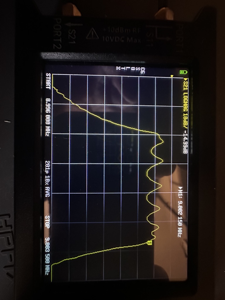
- Bandpass filter is the QRP Labs design, just with parts I had laying around. Don't have as nice of capacitors as his kit (they are no-name trimmer caps) and the bandwidth is more like 2MHz vs his 1.4MHz, but the insertion loss was about the same (-1.75dB) and does the job.
- I have one RF amplifier in - an AliExpress "low noise 30db" thing. (I need to remeasure what gain I'm actually getting at 9V.) Will probably replace for a MostlyDIYRF IF amp that has AGC.
- Both mixers are AD831 boards off of Aliexpress. Want to see about swapping them out for some of the DBMs I built when playing with the SolderSmoke DCR.
- The audio amplifier is one from SparkFun, a class D amp based on the TPA2005D1 chip.
- The speaker is a Jameco Valuepro "4" 8 Ohm 5W 800Hz-10kHz Paper 97 dB"
- The IF bandpass filter is the Mostlydiyrf one that I posted about before. I made little stand-alone matching transformers for it. I'll probably swap it out for a similar crystal filter I made years ago.
- The VFO/BFO is from a MostlyDIYRF "UDVBM-1 Universal Digital VFO/BFO". Will replace with my own arduino/si5351/display setup if I actually box this up, as this board is really nice for mocking things up and would like to keep it out for that. Also, the code he has for this has a few things I'd change (the VFO shows the actual frequency, not the frequency+BFO, and the "click to change what digit you are changing" doesn't go high enough). There are a lot of libraries out there or might roll my own.
No matter how many times I think about it, figuring out what side of the IF filter to put the VFO/BFO always does my head in, and of course I had it on the wrong side to start. I like using FT8 to test, as you always know there are going to be strong signals there, and if my iPhone decodes it, we're probably good to go.
I think next step is that I want to make it a transmitter. Really just need to make an amplifier for the microphone, use the QRP Labs 10W amp (must remember to take out the 40M bpf it has in it). Use one of my various RF amps to get the power up enough to drive that. I have various LPFs I've made over time sitting around.
Then see about making it a transceiver. I have some relay modules that are ready-to-use with microcontrollers (have the diodes in for the current spike, etc.) I think will be mostly figuring out how I want to attach different parts, updating the code to handle switching, etc. The whole "boxing and socketry" thing is the part I'm least good at, so might take quite a while to get to it.
Anyway was well pleased