Sunday, January 19, 2025

Preliminary success with new devices

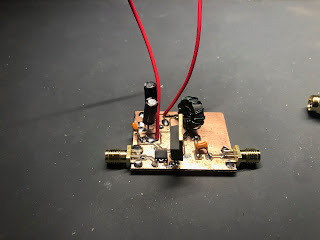
 A nice chap that goes by Stretchyman put me onto some devices I was not aware of.  Specifically, the UCC27614DR gate driver and the GAN111-650WSBQ GaN FET.  I had a go this afternoon with throwing them together in a similar layout as my last try with the IRF510.

So far I'm getting good results.  Out of the gate I was getting 10W out with decent efficiency.  I haven't let it run long yet.  

As an aside, I noticed that my probe was having an effect when I put it on the dummy load.  Switched it to 10x and that fixed that.


Sunday, January 12, 2025

A lot of progress over the weekend

 I haven't been writing this down, so it is hard to remember all I got done over this weekend.

I spent some time trying to build this HF PA.  


I was not getting at all the output that I was expecting.  And also found that the drive waveform looked weird.  The guy who designed it was super nice and responded to my emails really quickly, but I couldn't quite figure out what was up.  But I did observe a few things

  • The drive waveform was "weird" when using my signal generator.  But it looked way better when I used the SI5351.  I'd like to investigate this more later.
  • The drive still wasn't as square as I'd like.  My theory is it is due to my construction technique introducing stray capacitance/inductance.  Want to look into rebuilding (maybe a pcb)
  • Even when I increased the power to the drain, the output power didn't increase.  Don't know what was up there.  One theory is that this isn't a good IRF510 - it was one from Radio Shack years ago, and I couldn't find my new ones anywhere.  Want to order new ones and try it.
  • I built a little adapter board where I could use 3 BS170s in place of the IRF510.  It does look like increasing the the drain voltage increased the power out here, which points to the IRF510 being bad.  But also want to investigate to make sure I didn't do anything dumb with the output transformer.

I also wanted to try the NCP81074A again.  This time I decided I would try with an actual PCB.


First time I've etched a PCB this century.  I have tried a few different toner transfer techniques (acetone/alcohol no-heat, various papers for heat transfer).  I ended up trying this paper, and it worked pretty well.  I don't think Brother's are supposed to be best for this, and my toner is running low, but it turned out ok anyway.  I used an iron on high for two minutes.  The edges weren't great and there were a few lines broken, so I filled in with Sharpie.  I used ferric chloride with a sponge (so I barely used any, and it was done quickly).  I checked with meter, and there was only one broken trace (that I fixed with solder).


And here it is populated.


Got nice results - looks like 85% efficiency.  I tried some different voltages, could get 10+ watts out.  I ended up putting a heatsink on, but turned it back down to 5W.  I can't quite tell how how the driver gets, and at 14MHz it seemed pretty toasty.  Will play more with different drive voltages, etc.

Overall, a nice result for the weekend!


Tuesday, January 7, 2025

10W amplifier - success!

 Woke up early this morning so was able to swap out the BS170s before work.  The hardest part was figuring out where they were :)

Well, also desoldering.  The wick works good in general, but isn't good at clearing holes.  But I managed to use the soldapullt on the other side of the board from the iron and it worked a treat.  Would have been good to have a third hand or a helper, but made it work.


On the plus side, I have output!  And gain!  But not as much gain as I should have.  

With a 13.8V power supply and 9v p-p from the signal generator, I was getting about 4.6W out (15.2 vrms).  I am unclear on if that is too much power input.  There are discussions on the forums about input impedance not being 50 ohms, so I'm not sure if that is 200 mW (at 50 ohms) or 25mV (400 ohms).  Should try to get a proper power input measurement...

But based on things in the forums, I increased the power, and was able to get 10W at 17v.  Can experiment more with the input power.  But, regardless, I fixed it!  :)


Monday, January 6, 2025

Another go at a QRP Labs 10w Linear amp

 I had a great time at the Minnesota Amateur Radio Technical Society meeting this past Saturday.  Great conversation, and free stuff to boot!  A beloved member had recently become a silent key (at almost 100), and his family had sent a bunch of his workbench stuff in to go to a good home.

Most interestingly, there was a 10W amp!

This is a QRP Labs 10W linear amplifier.  Which I know about because I've built one, but never got it quite working.  (I can't find my notes about the issues I was having).  So this is exciting.


First of all, Mert did a way better job of boxing things up than I ever have.  


On the inside, I found that there was a low pass filter on the output.  Measuring with the vna, it looks like it is for 7MHz.  Also, the transmitter powers the bias when the /tx pin is low.  He has a phono jack for this, and made a little shorted plug to keep it on.  Nice!

I hooked it up to a dummy load and powered it on with no input, and it looks like the bias is already set correctly.

Unfortunately, when I applied signal, nothing came out the other side.

Poking around, the bias at the irf510s looks right, but there was no signal.

The input BS170s have power and signal, but no output.  So, those look blown.  It got late tonight, so I'll have to wait to swap them out for another day.


Friday, January 3, 2025

Towards a working class E amplifier

 I've had a few attempts in the past of building a class E amp, but never quite got the right results.

I dug out an old board where I tried to replicate the NS-40 and decided to try a different drive circuit.  I took out the oscillator and drive circuitry and replaced it with a NCP81074A gate driver.

It somewhat worked - I was able to get some power out.  But it isn't as efficient as it should be because the gate drive is ugly.  Need to look into it more.


The circuit


The ugly gate drive